
Building in the Concrete Jungle
Because downtown streets are difficult to dig up, laying fiber there is costly.
Microduct technology offers a good alternative for hard-to-build areas.
By Gordon Caverly ¦ Mid-State Consultants
Imagine that you are designing and building a fiber-to-the-home project that will pass 4,200 homes in a wellgroomed, well-maintained, quintessentially rural community. The four-block downtown area has new concrete and asphalt that was placed within the last three years. There is very little greenbelt area, and all the utilities are underground in their own conduit systems. There are no aerial pole lines. Most of the buildings have businesses on the street level and residential units on the second floor; the businesses serve the local community, and the last thing they want during an economic downturn is disruption. They don’t welcome the idea of your reducing traffic flow to their locations. The city fathers and managers are adamant that you don’t destroy their new concrete and asphalt facilities, disrupt their way of life or enrage the local business population. However, they are very attracted to the new technologies and service offerings that come with an FTTH project. You research your placement options with the city and review the downtown underground utility drawings for all the new facilities. Then you are told, “We did not receive any as-built drawings of the duct placements.” You have no clue where the facilities are located under 9 inches of double-mesh concrete sidewalk and new asphalt! Unfortunately, this is a very common scenario. Everyone is trying to protect their interests in all the facilities. Business owners want FTTH services, but they don’t want the streets and sidewalks torn up, which would cause major service disruptions. The city wants to protect its new concrete and asphalt; it is also interested in where you will place the fiber and how it will be able to locate and work around the fiber. Utility firms (power, cable, telephone, water, sanitation and so forth) don’t want their facilities dug up, cut into or directionally bored through, which could cause them significant expense and service outages. This is the telecom placement Catch-22: Yes, we want your service. No, you can’t dig there. No, the city doesn’t want a lot of disruption. Yes, we want to know where you are working. No, digging up our new concrete isn’t feasible. By the way, when can we have your service? In one word: frustrating!
The Options
The town I’ve described is real. My company, Mid-State Consultants, was hired to do FTTH engineering there. Usually, when a service provider asks us to help deploy its technology in a concrete jungle with limited greenbelt area and virtually no access to buildings short of the concrete and brick walls, our engineers will look for any of the following:
- Existing underground ducts
- Aerial options
- Open trench and new lateral duct placements
- Ducts that can be leased from other service providers
- Opportunities for directional boring and potholing (digging one or more small-scale test holes) or section cutting and replacing concrete sidewalk squares
All these methods require investing time and money to place and then maintain the plant. There may be additional costs later on if the ground settles or the duct is hard to find. In this case, however, all the usual methods were ruled out.
- No existing underground ducts were available and usable. (To be usable, ducts must be complete and compatible with the design.)
- There was no contiguous pole line available, and the line that was available was congested with existing aerial providers.
- The city refused to allow open trenching because it would be extremely expensive and cause massive business disruptions.
- The service provider did not want to share a joint duct with a competitor, and in any case the competitor’s duct system was not compatible with our client’s design.
- Directional boring and removing and replacing concrete sections would also have been extremely expensive and disruptive to businesses. Without as-built drawings, existing facilities were not locatable, and there was a very high chance of hitting other facilities and creating a significant liability. These costs were estimated at $400 per 4-foot-square concrete square and $9 to $13 per foot of directional bore. Additionally, there would still be open cutting at the building for pedestals.
Enter Microduct Technology
Once we established that none of the usual methods would work, we began to evaluate microduct technologies. Microduct technology – in which ducts are placed less than a foot below the roads, sidewalks or other traveled surfaces in narrow trenches or “slots” – is still relatively new, and the concept is a radical change for everyone involved. However, it should seriously be considered in any area that is a concrete jungle or has large areas of asphalt covering. Like most state-of-the-art technologies, designs and new concepts, microduct technology is going through a phase of evaluation and scrutiny. But I believe this new fiber technology design and construction method will eventually achieve total acceptance because of its small size, ease of installation and ease of placement and relocation. The design and construction of microduct is very simple and easy to implement: The engineer identifies all building locations for the terminal placements, picks a path that returns to the feeding terminal and routes it in a configuration that is conducive to picking up any other terminals in that path. The design parameters for this technology are critical; engineers must understand the placement limitations and the blowing distances of the fiber, depending on which duct configuration they select.
Two kinds of microduct design are currently on the market. In a split-duct configuration, the fiber is laid into the split duct at the same time the duct is installed, after the slot cut in the concrete or asphalt is opened. With this configuration, the provider actually places the fiber cable in the duct and can choose a fiber size appropriate to its service needs. A sealed-duct configuration offers a waterproof and airtight design. The microducts plug together, forming a seal that keeps out water and air, and the fiber is blown in only after the duct has been placed in the ground. This configuration requires specially designed microfiber that is blown into the micro innerducts within the sealed system. Providers can choose various sizes of fiber for use in this system as well. Both system architectures offer transition junction enclosures in the vertical and horizontal plane and splice or junction closures to provide a flexible configuration along the selected pathway. For either type of system, the key to a solid design is up-front engineering planning and an understanding of the goals for the service area. Consideration of the strengths and limitations of the selected duct system is also necessary, as is an understanding of the design parameters for both the duct system and the parallel fiber system.
After evaluating the systems on the market, we selected a sealed-duct design from Lite Access Technologies (www.liteaccess.com) as the most suitable for this application.
Design and Implementation
We found that coordinating the design directly with city offices, water and utility departments and all the affected businesses was absolutely imperative. Once our design was being implemented, we learned a second lesson: Don’t take for granted anything the city says about rights-of-way, property lines, ownership or who has authority to do what on whose property. Engineering companies should undertake their own thorough title searches of downtown properties to understand who owns the businesses, who owns the properties the businesses occupy and where the property lines are. Only after coordinating all the permissions and rights-of-way with business owners and property owners can they confidently move forward with their designs and obtain approvals and signoffs from city offices.
The engineering design should encompass multiple layers of engineering work prints, including one that specifically identifies the location and footages of the duct system, the splice locations and any duct extensions up the wall to a terminal. The print for a split-duct system must show the cross section of the duct because it comes in multiple configurations and the spare ducts as well as the occupied duct must be tracked. With a waterproof, airtight duct system – which is a sealed system with microconduits in an outer shell into which fiber is blown – each microduct should be color coded. The drawings should identify the fiber corresponding to each duct and show how each microduct is configured and spliced at those locations.
Both types of systems come in various configurations to accommodate pathway design, slot trench size and splice juncture considerations. In a typical design, digital pictures should accompany the detailed work prints and as-built records. The as-built drawing should be a bird’s-eye-view map with the duct route identified with splicing locations. This map should be provided to city offices and utility departments for their use in locating and tracking the service provider’s facility.
The second engineering schematic should show the fiber network with cable counts, footages and terminal and splice locations. In the split-duct configuration, it may be possible to place multiple fiber cables of various sizes specifically designed for this application. As of this writing, the closed system offers a choice of blowing 12- to 96-count fiber into each microduct. In both applications, it is necessary to assign engineering nomenclature to the fiber cables and counts that are specifically related to this architecture so it can be easily tracked and documented in the records.
Construction and Project Management
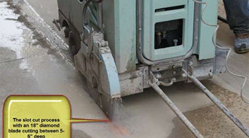
In constructing this project, we used a slot-cutting machine that had an 18- inch diamond cutting blade. (Larger blades are available.) The slot was placed directly behind the street curb and its path included any existing slot cuts in the sidewalk. This machine easily navigated reasonable curves in the curb and was very effective in notching out a ½-inch-wide slot 5 to 8 inches deep. This depth allowed us to place the microduct just below most of the concrete sidewalks, butted up against the street curb for additional protection. Placing the duct in the existing expansion joints behind the curb and in the sidewalks allowed effective and efficient cleanup afterward and resulted in a completed project area that appeared to be undisturbed. We used a filling product called Perma-Patch to backfill the construction slots. Perma-Patch (www.permapatch. com) is all-weather, all-season permanent patching material. Its effectiveness and lifespan increase as it is driven on and placed under pressure, ensuring a solid restoration or repair operation. It is also very easy to remove and replace at a later date, should the need arise. The benefits of this microduct technology approach:
- The service provider’s facility was above the other utility infrastructure.
- The facility was easy to identify and protect.
- Restoration and repair would be easy.
- In case of street replacements or resurfacing, removing and replacing the duct would be possible.
- Businesses and customer traffic were disrupted as little as possible during the installation.
- The approach was cost-effective compared with other construction methods.During construction, the work site was easily cleaned up each day.
- Multiple pathways allow future fiber reinforcements.
The potential negatives of this design approach:
- The service provider’s facility was above the other utility infrastructure. (This is a double-edged sword.)
- The cost of this project was $18 per foot (price quotes ranged from $18 to $40 per foot) plus charges for add-ons such as circular cut holes and miscellaneous materials. (Most of the material was included in the per-foot price.)
- The city and the service provider had some concerns about their fiber facility being placed 6 to 8 inches below the road surface when the norm is 36 to 48 inches.
- I would have spent more time on the design and on understanding the metrics and logistics of this design before moving forward.
- I would have researched the blowing and pulling distances of the fiber and the associated logistics of that process instead of relying on the contractor for this information.
- I would have completed an in-depth review of the rights-of-way associated with the downtown properties.
- I would have considered and designed all splicing locations andfunctions more exactly, with specific blowing distances within my predetermined specifications.
- I would have spent more time with the contractor, ensuring that it was prepared and equipped to construct a project of this nature. (The contractor on this project was not new to this type of construction but was new to this type of product; ultimately, the contractor was excellent to work with and went the distance to ensure that I received a quality and timely product.)
Summary and Reflections
I believe this technology will become commonplace and will, at the very least, be necessary in tough, hard-to-build areas. In concrete-covered locations, traditional methods of placing stateof- the-art fiber facilities are logistically difficult, physically challenging and too expensive and time-consuming. Taking into consideration the costs, the business disruptions, the liability of utility hits and all the other problems associated with traditional construction, including time and cleanup costs, microduct technology was the least intrusive method we could find for this project. In retrospect, this methodology was the best for a downtown landscape and the city business environment, including the service provider.
Of course, there are a few things I might have done differently:
The final evaluation of this architecture and technology will have to wait for the passage of time. Because it must adhere to an existing landscape, the design must be precise, and the interfaces with the city, businesses and the landscapemust also be precise. However, microducttechnology allows a degree of flexibility that is unequalled by traditional methods. In the future, when a sidewalk is replaced or a parking lot resurfaced in the city where we installed the microduct, this technology will be tested. However, I believe both engineers and construction crews will have an easy time moving, replacing and modifying the microduct as needed. If you asked me today whether I would recommend this technology to my clients, and whether I feel confident about this design and strategy for building in the concrete jungle, the answer would be a resounding yes.